The voltage regulator module (Voltage Regulator Module – VRM) is one of the essential hardware components in the general structure of a motherboard system. However, VRM has not received much attention for a long time. and even folks don’t even know its existence. In theory, VRM makes sure your CPU or GPU receives the cleanest power source possible at a consistent voltage level. In this article, we are going to talk about What is VRM and How it Affects the Processor. Let’s begin!
Poor VRM can lead to degraded performance as well as limiting processor performance whenever it loads tasks. And may even lead to unexpected system shutdowns, especially when it is Overclocking. In fact, before the known causes of software, the weaknesses in VRM design are also thought to be related to Apple’s recent adjustments to the i9 MacBook Pros.
Let’s see below what a VRM is and how it affects processor performance.
Contents [hide]
What is VRM
VRM is a circuit that converts DC voltage from this value to a lower value and at the same time, it also keeps this voltage within the permissible limits at different load levels. Its other name is ‘DC to DC converter’.It is impossible to say that this conversion function is actually a new technology as it has a lifetime equal to the life of the electronics and electronics industry as well. It is also easy to see that there are many VRM circuits on the motherboard of the computer. It provides power to the CPU, RAM from + 5VDC, or + 12VDC source voltage to the lower voltage that the CPU and RAM also have. That can work.
How does VRM work?
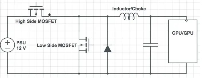
The VRM in the computer power supply is actually a DC voltage stabilizer. That operates according to the PWM modulation method just the same as the main power PWM circuit. It also has equivalent component components like oscillator IC, Mosfet, PWM coil, and filter capacitor.
The first job of the VRM is to convert 12-volt power from the computer’s power supply into a voltage so that the microprocessor can be used. For microprocessors, this voltage mostly ranges from 1.1V to 1.3V. Sophisticated electronic devices within each microprocessor can easily fail to achieve the necessary effect because of power reasons. Accuracy is also important whenever powering the processor and the required voltage must distribute as accurately as possible. That’s why the structure of VRM is much more complex than a simple wire segment actually. However, the “heart” of VRMs is basically a buck converter – a device that accurately decreases the voltage to the appropriate level.
VRM uses the following three components to perform its work:
- MOSFET (that is short for Metal-Oxide-Semiconductor Field-Effect Transistor, which means “Metal Oxide effect transistor – Semiconductor).
- Inductors (also called inductors).
- Capacitor.
There is also an integrated circuit (IC) to control them all, sometimes called PWM controllers. Here is a simple diagram of a single-phase VRM system:

Multi-Phase VRMs
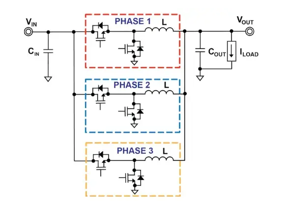
Modern computers need more than a single phase VRM. Modern power systems actually use a multi-phase VRM. Multiple phases spread the power load over a broader physical area, which reduces heat production and stress on components. As well as providing other electrical improvements related to efficiency and also per-part costs.

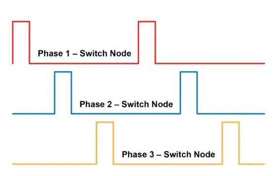
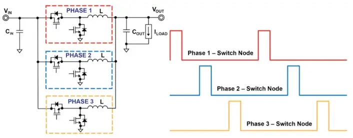
Each and every phase of a modern multi-phase VRM supplies a fraction of the power required. That takes turns to provide power to the CPU. Taken individually, each phase gives a brief moment of power, visualized as a square-shaped wave.

Each phase’s burst of power is staggered from the last so that while only one phase is operating at a time, the total amount of power never changes as well. This, in turn, produces a smooth, reliable power source – the “clean” power needed for a CPU to function optimally. You can also see a simplified system in operation below.

VRM Phase Numbering and Truth in Advertising
VRMs are typically sold as something such as “8+3” or “6+2.” The number before the plus actually indicates the number of phases dedicated to cleaning power for the CPU. The number after the plus indicates the VRM phases left to power other motherboard components such as RAM.
When the first number is greater than 8, like “12+1,” “18+1,” or even higher, then the manufacturer mostly makes use of a device called a doubler. A doubler allows them to multiply the advantages of the existing phases without building additional phases into the board. When this is not really as effective as wholly separated phases, it does allow for some electrical improvements at less cost. And since it also allows manufacturers to raise a buyer-facing number at small expense to themselves, they mostly take advantage.
Some manufacturers, Gigabyte especially, have also begun to label phases wired in parallel because if they are two separate phases. In fact, this is actually one phase duplicated. Its electrical signals are synced instead of staggered, removing many of the benefits of a true additional phase. But manufacturers are mostly willing to bend the dictionary definition of a word if it suits their purposes. Unethical, surely, and perhaps legally dark as well. However, as always, cavet emptor.
How Does VRM Improve Performance?
Overclockers should seek out a VRM that is made from reliable components. If its components are cheap, then they may fail to supply sufficient voltage under load, which will cause surprise shutdowns. The most variable components are capacitors and also chokes. You have to look for leak-resistant capacitors. These are mostly marketed under names such as “Japanese Capacitors,” “Dark Capacitors,” or “Solid Capacitors.” High overclocks will need better chokes as well. You can find this named as super-ferrite chokes (SFCs) or “Premium Alloy Chokes”. as well Also look for heatsinks over some or all MOSFETs – finned, if it’s possible.
Imagine, that the main power transformer of the power supply is a water tank. With the normal power supply that has 3 compartments corresponding to 3 nozzle heads, 3 main power lines. So that each compartment (capacity each line) will be lower than the total capacity of the container (total power supply capacity). For a VRM power supply, the container has only 1 compartment and 1 12V water supply, so that it can be said that the total storage capacity will be equal to the total capacity for the 12V line. 12V power supply for The remaining 2 lines is through the VRM circuit or it can be said that the other two lines are a load of 12V line. In theory:
PSU capacity = Capacity 12V = Power 5V = 3.3V capacity provided that 2 of the 3 lines actually have zero load.
Further
Well, if you have 2 power supplies with the same power level, then the VRM power supply will always give you a higher level of power for each line. Based on the needs of the new system, which currently uses a lot of energy from the 12V line, this will actually help you not need to buy a larger power supply.
In order to make it easier to understand, we can compare the two different power sources of AcBel, R8 607W. That does not have VRM, and R88 features VRM for both 5V and 3.3V lines. We can see that although the same power level is 600W, the total output (max output) of each power line, R88 actually has a higher capacity. The 12V R88 line is 540W @ 45A and R8 only has 480W @ 40A as well. When you want a 12V power supply with a capacity of 40A, along with no VRM power supply you have to choose to buy a power supply with a capacity of over 680W. However, with a VRM power supply, only a 600W power supply is enough.
Conclusion
Alright, That was all Folks! I hope you guys like this VRM article and also find it helpful to you. Give us your feedback on it. Also if you guys have further queries and issues related to this article. Then let us know in the comments section below. We will get back to you shortly.
Have a Great Day!
Also See: Essential Tools To Stress Test Your CPU


